
Arduino Nano ESP32 Nixie Clock conversion
Some years ago I decided to follow along and assemble my own example of a Nixie Clock, specifically following the design of GreatScott - written version here.
While my slightly modified version with a more accurate DS3231 clock and automatic DST detection worked well enough, adjusting the time, whenever it was needed, was cumbersome since a partial disassembly of the enclosure was required, followed by the need to flash the microcontroller with a program specifically used to set the time on the RTC, and a final flash to the “normal” program.
A change-over to a more modern ESP32 microcontroller with network connectivity seemed a good idea, enabling either automatic time setting through an NTP server.
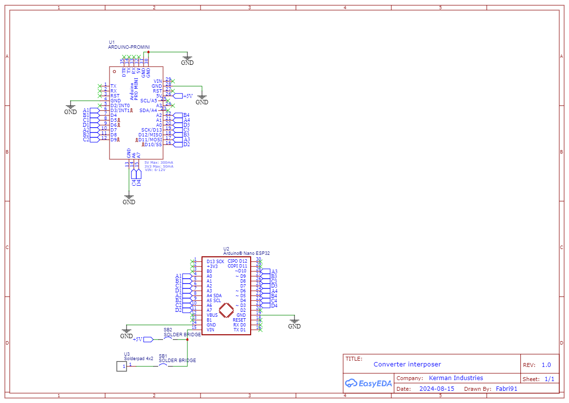
In order to avoid redesigning the PCB carrying the tubes themselves, and avoid having to desolder and resolder them, I designed an interposer board that makes it possible to use an Arduino Nano ESP32 in place of the original Pro Mini.
Since the Soviet K155ID tube drivers used accept 2V as a minimum voltage for the input, they work well with the ESP32’s 3.3 GPIO voltage in addition to the 5V GPIO voltage of the original Arduino Pro Mini.
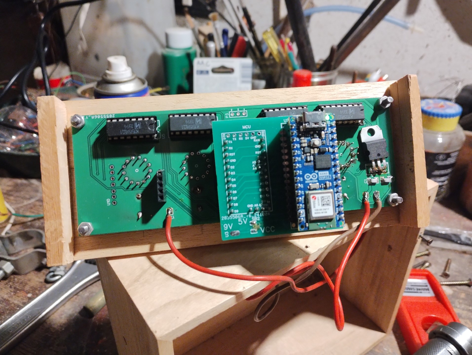
The interposer board is a very rough design, being an amateur at best when PCB design is concerned, with its footprint overhanging on one side the original board’s area.
Two solder jumpers enable the selection of input voltage: either 5V through what would be the original Arduino Pro Mini’s 5V power supply pin, or through a pad to be connected to the clock’s existing 9V voltage.
The power supply specifications of the Arduino Nano ESP32 recommend a voltage range starting from 6V for the external power supply, but 5V seems to work good enough in practice.
Two sketches are provided:
- NixieTest_NanoESP32 cycles through the numbers 0 to 9 to test the correct functionality.
- NixieClockWiFi_NanoESP32 is the sketch proper, with basic functionality but with NTP timesync.
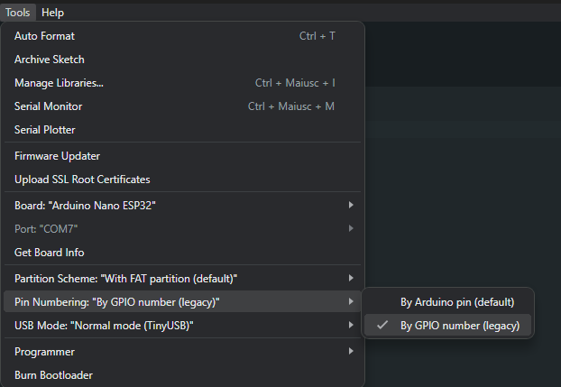
Important: the pin numbers are in the legacy GPIO numbering scheme, so the following setting must be used:
Resources: